Original by Stuart (MySolderIsOlder)
So, further to earlier discussion under the thread 'Pre modded servo boards for ESCs', I did some more testing over the weekend. Not as much as I would have liked (weather was OK so had no excuse not to be repainting window frames ) but enough to spark my interest. As per that other thread, idea was to test use of the tiny speed controllers taken out of servos which were designed with a) continuous rotation, and b) digital control instead of variable resistors.
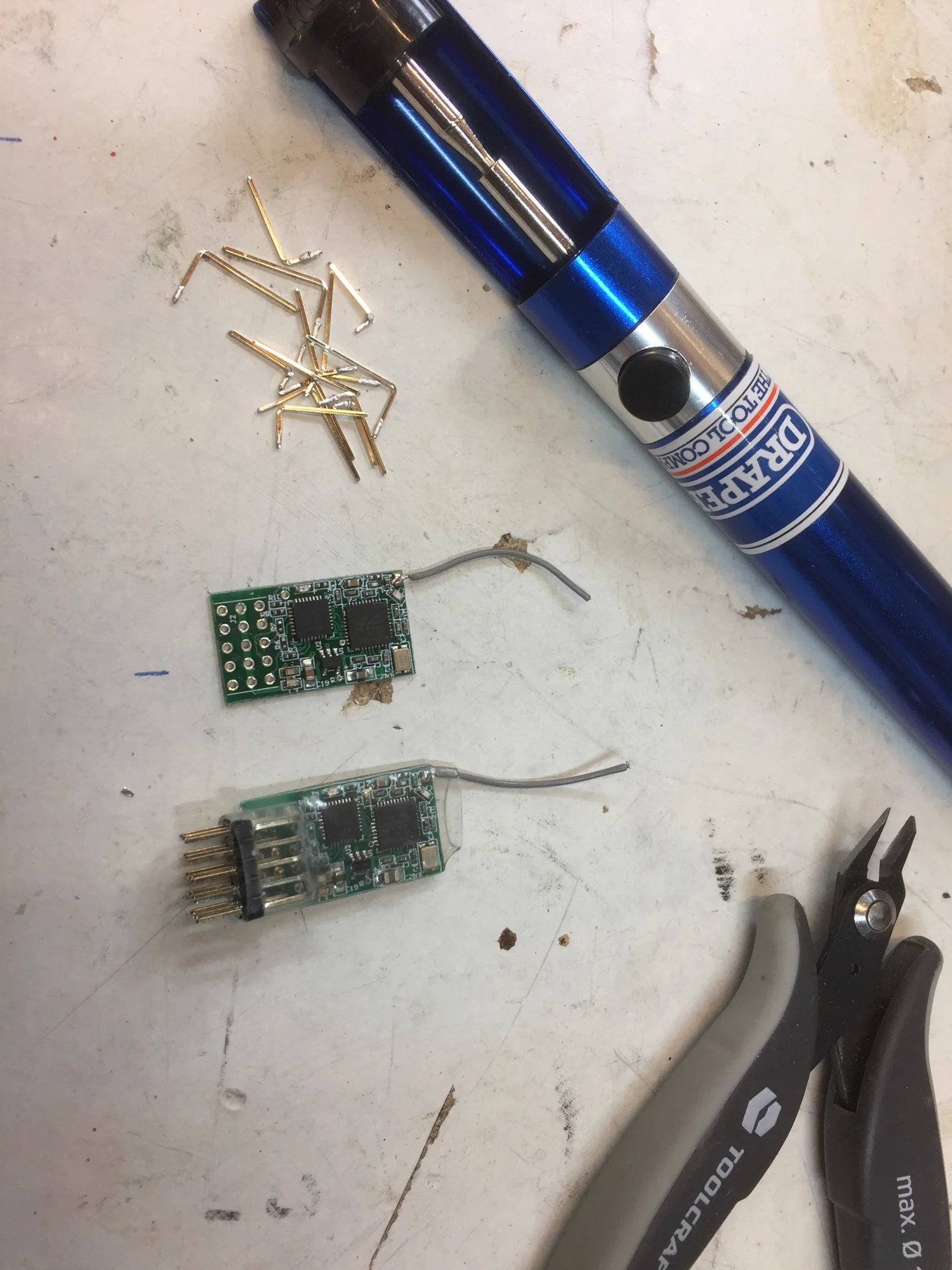
In theory, such controllers should be suitable for use as single-channel reversible ESCs with no further tinkering. I had two such controllers to test, taken from the Dorman RC servos (DM-S0090D-R ) suggested by Ant Ipodean and the FT90R from Feetech (former are ~£1.50 each from AliExpress when bought in ten packs, latter are around £3.00). Both are pretty small boards, though the Dorman's (top of each pic) are smaller:


The Feetech has the motor soldered directly to the board, hence the odd shape and large solder-through holes.
After careful retesting I basically got the same results noted previously, i.e. the Feetech boards behaved perfectly (clear dead-band with 0v and full voltage at stick limits) while the Dormans showed around 0.5v in 'neutral' and didn't provide full voltage to the motors. These results were the same regardless whether I had a motor connected to the output or just the digital multimeter, so I don't think it could have been a back-resistance issue. Testing with just a motor, the Dormans caused a slow rotation (10-15 rpm) in neutral and were noticeably slower than the Feetechs at full throttle. No idea why I'm getting such different results from Mike with the Dormans boards - possible I'm doing something wrong or maybe I just got a duff batch. If there's anyone for whom the slight size and cost advantages are crucial then it's certainly worth persevering with them but personally I'm going to forget about the Dorman servos for the moment and stick with the Feetechs.
So... on with my efforts to bodge together a "Poor Man's Nano" or PMN as I'm now calling it. Goal is to have a reasonably consistent little package, as cheap, small and light as possible - but also reliable and easy to drive. I noticed with these controllers there is a slight delay switching from forward to reverse but we're talking less than half a second - so don;t think it will impair driveability in real world situations. Other than that, responsiveness seems excellent, with a proper proportional response as you move the stick gradually through its range.
First step, disassembling all the servos was strangely satisfying. They're generally very well put together and dismantle cleanly:

Removing the boards was pretty easy too - just hold the motor in a mini vice, melt solder on one side while gently bending the other way. All boards came off cleanly.

Then just cleaned out the old solder using a simple solder pump (very easy with through-soldered holes if you hold the iron on one side of the board and the pump on the other).
So - that's the ESCs sorted, now just needed receivers. In ideal world, I'd stick with the OrangeRx R614XN as they're the smallest DSM-compatible PWM options I've ever found - only they're a bit pricey at around £10 each and currently unavailable. Second best option, which I've come to rely on most of the time, is the Redcon CM421 4-ch Rx from BangGood. These are cheap (just bought a batch of 10 for £4.90 each), rated up to 10v (so no need for a BEC or voltage limiter when used with 2S LiPO) and pretty compact - except for the row of pins at one end. Futaba connectors are no good if you're after a really compact package (I'd rather have nice holes for through-soldering) - so they had to go. Having tried this a few times now, I find the best option is to slide/cut off the plastic 'comb'-like widget that holds the pins together, then clamp the board in a vice and desolder the pins one by one. It's then easy to clean out the holes using the solder-sucker (again - heating the solder from one side of the hole and sucking from the other). Takes me about 20 mins to complete. Here's how they look before and after pruning:
It's then a case of carefully trimming the ESC leads down to length and stripping the ends (with such short leads be very careful not to pull the whole insulation sleeve off, like I did a couple of times!) and soldering them onto the back of the Rx board, along with any other required leads. In my case that's the power supply (red & black) throttle-channel signal pin (white) and bind pin (grey - this needs shorting to GND to initiate binding), plus blue & yellow for the motor leads. I used 24AWG silicone insulated wire throughout:

After a quick test, then wrapped the individual ESCs in heat-shrink, folded everything into place and wrapped it all up in clear heat shrink (so I can still see the Rx LED).


Resultant package is about 31x17x9mm and weighs 5.5g (including wires). So... not quite as dinky as a real Nano but small enough and cost less than £12 to make - so it's good enough for me! Incidentally, that tiny plug & header in the photo is a JST-SH 2-pin micro connector (1mm pitch) which I'm experimenting with for binding - plan is to have a header with the pins shorted so I can just slide that on to put it in bind mode. Weighs next to nothing and less likely than a tiny slide switch to engage accidentally.
Managed to put together two PMN units in one afternoon and both worked a treat.
Tested using 2S LiPO and one motor per controller. Left it running full speed for 5 mins - no noticeable overheating issues. Obviously, this kind of bench testing is no substitute for the real thing, so plan is to make a quick & easy 4WD antweight and let my son thrash it around our test arena for a while. If it survives him an his little friends, it should survive anything.
So finally...
just tested the other type of Feetech FT90R esc as arrived today; what I’ll call the “Feetech short board”.
This time, instead of the longer boards with the motor soldered on directly, the 20-pin quad-flat package micro and the AM1096 motor driver, these new ones have smaller (9x12mm) boards with short leads to the motor, an unmarked 8-pin DIP micro and TC118S motor drivers...
Good news is it’s got a clean dead band and supplies full voltage to the motor. Bad news is that the proportional response sucks - not much gradation between off and full throttle.
So, better than Doman blue boards, roughly on par with Doman green board, not a patch on Feetech “long board”.
Here are the front and back views

Firstly, I think I now know why I was seeing a much reduced voltage at the motors using the DomanRC boards. Standard DSM Tx/Rx combo is meant to give a control pulse in the 1-2ms range, with 1.5ms as zero - and I think that's pretty much what I get from my Spektrum DX6i with the default -100% to 100% endpoints. That was giving me +/- 4v with the DomanRC c/r servos. With the Digital Servo tester, which runs from 0.8-2.2ms, I was getting nearer 5.5v at the ends, and I was able to get something close to that after setting the Tx endpoints to 125%. In other words, looks like these DomanRC servos are designed to work over a wider than usual range of pulse widths. The description for one of their other digital servos (a 270 degree version) specifies a PWM range of 0.5-2.5ms is required for maximum movement - so I'm guessing with the 360 degree version you'd need a similar PWM range to get maximum voltage (100% duty cycle) to the motors.
Secondly, using the 'green-pcb' Doman board that Antipodean sent me, I got a pretty good proportional response over the full range. Dialing the tester up from 0.8ms to 1.4ms, voltage changed in a reasonably linear fashion from -5.5 to -2.3, then dropped suddenly into the dead band, kicking back in again to +2.3v at 1.6ms. So, a small cliff-edge either side of the dead band but still very good.
Doing the same test on the two variants of the Feetech FT90R boards, the long board showed a healthy degree of proportionality - steady -6.2v (full battery voltage) from 0.8 to 1.3ms, then a very smooth slope all the way down to zero at 1.45ms, picking up again at 1.55ms. This matches my experience of driving my test bot utilising these boards, where I was able to make it crawl along with a gentle stick movement but pushing the stick beyond about half way resulted in full speed. Might even be worth reducing the endpoints in this instance to increase the proportional stick range.
By contrast, the FT90R short board is about as proportional as our FPTP electoral system - it was delivering full voltage from 0.8 to 1.45ms then dropped to zero almost immediately, jumping back up to full voltage again at 1.55ms. Basically, it's on or it's off with a difference of maybe 30 microseconds in pulse width between the two extremes (it was quite hard to measure but the 'proportional phase' only seemed to be around 1.44-1.47ms so I don't think any amount of Tx tuning is going to help there.)
So... to conclude (phew!)... either the Feetech FT90R long board variant or the DomanRC 'green pcb' variant should make a fine ESC, though with the latter you'll want to ensure your Tx/Rx can go well beyond the 1.0-2.0ms pulse width range in order to get maximum speed. By contrast, the Doman blue PCB (no dead band) or FT90R short-board (no proportionality) versions should be avoided. Trouble is of course, you won't know which variant you've ordered until they arrive!
Promise I won't say any more about this, though I will be interested to hear other peoples' experiences of these servo boards.
Stuart
Regarding the differing experiences when testing the Doman servo boards, thanks to Mike (Ant Ipodean) the mystery is solved. He very kindly airmailed me one of his stock of Doman boards to test.
When I repeated my tests using Mike's board, my observations were the same as his, i.e. there is a clear 0v dead-band in the middle, at full stick the voltage is 2-3v below supply voltage when connected with just a multimeter but only around 1v below supply when the voltmeter is connected in parallel with an N20 motor. By comparison, my version of the Doman boards had around 0.3v (enough to turn a motor) in neutral and were 2-3v below supply regardless whether a motor was connected or not.
(I'm guessing that on both cases, the voltage drop is because the PWM isn;t reaching 100% duty cycle but with no access to an oscilloscope I can't confirm that. By comparison, the Feetech boards I've been using deliver the full battery voltage to the motors.)
Clearly, these differences are not accountable for by normal manufacturing quality variation - and make a huge difference to whether these servo boards are suitable for ESCs or not. However, it was immediately obvious on inspecting the boards that Doman must have changed design and/or suppliers at some point - the PCBs are not even the same colour and have a number of track differences. In terms of the SMD components, always hard to get definite IDs but...
Mike's Doman board (green PCB)
Regulator: V1QG
Driver: FZMOS-5X
Other: 2x resistors, 3x capacitors, unmarked 8-pin microcontroller
My Doman boards (blue PCB)
Regulator: 662x
Driver: FZMOS-2
Other: 1x resistor, 3x capacitors, unmarked 8-pin microcontroller
Spot the differences in these front and back views; my board is the blue one on the left in each case:


So.... hard to say whether it's worth buying the Doman servos for use as ESCs as it all depends which version they send you. Chances are, if you get the green board you'll be but if you get a blue board, you'll be No idea whether the blue boards were a permanent change or maybe just clearing older, faulty stock during temporary supply difficulties - but I'd be v interested to hear other peoples' experiences.
Personally, I'll stick with the Feetech FT90R boards (see other thread "Follow up on Digital CR Servo Board ESCs" for details). They are twice the price (£3-4 each from AliExpress, depending on quantity) and slightly longer - but being a well established brand, they should be more consistent and in all my testing so far they've been impeccable; no DOA units, clear dead band, full supply voltage to the motor and excellent proportional response.
Thanks again to the Auckland Antmeister for his assistance in clearing this up - and to Hogi for setting me on the 'pre-modified continuous rotation servos' path in the first place!
Stuart